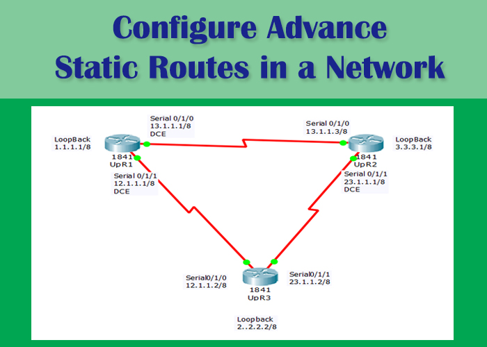

In this Cisco lab we will demonstrate the configuration of static routes using packet tracer in a slightly more complex network in order to get more learning and understanding of how static routes work and function, while highlighting the crucial points which must be followed for a network to function properly and desirably.
You should note that in this lab we will not be spending much time on the basic configuration of router’s serial interfaces, for basic configuration you should follow ” how to configure static routes in Cisco packet tracer “.
Advance Static Routing Lab Overview :
3 Cisco routers connected to each other through serial interfaces. Each router will be directly connected to two routers and three networks. We will setup three DCE serial interfaces for clocking and synchronization, and will configure three static routes on each of the three routers. Before heading to the configuration of our routers, you may want to learn setting and changing hostname of a router, setting console password, telnet password, cisco enable secret password, configure motd banner, configuring serial interface, saving and erasing configuration. We will follow the network diagram shown below, you should draw this diagram on a paper to follow this Lab.

Basic configuration of Router UpR1:
Assuming that you are familiar with the basic configuration of routers, we are not going to explain the commands used here in detail because we have already did that in the previous tutorials.
Configuring serial 0/1/1 interface of upR1:
upR1(config)#interface serial0/1/0
upR1(config-if)#ip address 13.1.1.1 255.0.0.0
upR1(config-if)#clock rate 64000
upR1(config-if)#encapsulation hdlc
upR1(config-if)#no shutdown
Configuring upR1 serial 0/1/1:
upR1(config-if)#exit
upR1(config)#interface serial0/1/1
upR1(config-if)#ip address 12.1.1.1 255.0.0.0
upR1(config-if)#clock rate 64000
upR1(config-if)#encapsulation hdlc
upR1(config-if)#no shutdown
Configure Loopback interface of upR1:
upR1(config)#interface loopback 0
upR1(config-if)#ip address 1.1.1.1 255.0.0.0
upR1(config-if)#end
Basic configuration of Router UpR2:
upR2(config)#interface serial 0/1/0
upR2(config-if)#ip address 13.1.1.3 255.0.0.0
upR2(config-if)#no shutdown
upR2(config-if)#exit

upR2(config)#interface serial0/1/1
upR2(config-if)#ip address 23.1.1.1 255.0.0.0
upR2(config-if)#clock rate 64000
upR2(config-if)#encapsulation hdlc
upR2(config-if)#no shutdown

upR2(config)#interface loopback 0
upR2(config-if)#
upR2(config-if)#ip address 3.3.3.1 255.0.0.0
upR2(config-if)#
upR2(config-if)#exit
Basic configuration of UpR3:
Router(config)#interface serial0/1/0
Router(config-if)#ip address 12.1.1.2 255.0.0.0
upR3(config-if)#no shutdown
upR3(config-if)#exit

upR3(config)#interface serial0/1/1
upR3(config-if)#ip address 23.1.1.2 255.0.0.0
upR3(config-if)#no shutdown
upR3(config-if)#exit

upR3(config)#interface loopback 0
upR3(config-if)#
upR3(config-if)#ip address 2.2.2.2 255.0.0.0
upR3(config-if)#exit
upR3(config)#
upR3r#
Checking Routing Tables of Routers UpR1,UpR2,UpR3:
For checking routing table of a router, the command “show ip route” is used. “Show ip route” is an enable mode command which displays all accessible networks and their routing paths whether they are directly connected, statically configured or configured through dynamic routing protocols. Note: you should be in enable mode to execute this command.
upR1#show ip route
Codes: C - connected, S - static, I - IGRP, R - RIP, M - mobile, B - BGP
D - EIGRP, EX - EIGRP external, O - OSPF, IA - OSPF inter area
N1 - OSPF NSSA external type 1, N2 - OSPF NSSA external type 2
E1 - OSPF external type 1, E2 - OSPF external type 2, E - EGP
i - IS-IS, L1 - IS-IS level-1, L2 - IS-IS level-2, ia - IS-IS inter area
* - candidate default, U - per-user static route, o - ODR
P - periodic downloaded static route
Gateway of last resort is not set

C 1.0.0.0/8 is directly connected, Loopback0
C 12.0.0.0/8 is directly connected, Serial0/1/1
C 13.0.0.0/8 is directly connected, Serial0/1/0
upR2#show ip route

Codes: C - connected, S - static, I - IGRP, R - RIP, M - mobile, B - BGP
D - EIGRP, EX - EIGRP external, O - OSPF, IA - OSPF inter area
N1 - OSPF NSSA external type 1, N2 - OSPF NSSA external type 2
E1 - OSPF external type 1, E2 - OSPF external type 2, E - EGP
i - IS-IS, L1 - IS-IS level-1, L2 - IS-IS level-2, ia - IS-IS inter area
* - candidate default, U - per-user static route, o - ODR
P - periodic downloaded static route
Gateway of last resort is not set

C 3.0.0.0/8 is directly connected, Loopback0
C 13.0.0.0/8 is directly connected, Serial0/1/0
C 23.0.0.0/8 is directly connected, Serial0/1/1
upR3#show ip route
Codes: C - connected, S - static, I - IGRP, R - RIP, M - mobile, B - BGP
D - EIGRP, EX - EIGRP external, O - OSPF, IA - OSPF inter area
N1 - OSPF NSSA external type 1, N2 - OSPF NSSA external type 2
E1 - OSPF external type 1, E2 - OSPF external type 2, E - EGP
i - IS-IS, L1 - IS-IS level-1, L2 - IS-IS level-2, ia - IS-IS inter area
* - candidate default, U - per-user static route, o - ODR
P - periodic downloaded static route
Gateway of last resort is not set

C 2.0.0.0/8 is directly connected, Loopback0
C 12.0.0.0/8 is directly connected, Serial0/1/0
C 23.0.0.0/8 is directly connected, Serial0/1/1
Now it is time to verify if the directly connected networks are accessible and can be pinged.
Ping Verification of Router upR1:
upR1# ping 1.1.1.1
Type escape sequence to abort.
Sending 5, 100-byte ICMP Echos to 1.1.1.1, timeout is 2 seconds:
!!!!!
Success rate is 100 percent (5/5), round-trip min/avg/max = 0/8/12 ms

upR1# ping 13.1.1.1
Type escape sequence to abort.
Sending 5, 100-byte ICMP Echos to 13.1.1.1, timeout is 2 seconds:
!!!!!
Success rate is 100 percent (5/5), round-trip min/avg/max = 2/4/12 ms

upR1# ping 12.1.1.1
Type escape sequence to abort.
Sending 5, 100-byte ICMP Echos to 12.1.1.1, timeout is 2 seconds:
!!!!!
Success rate is 100 percent (5/5), round-trip min/avg/max = 2/8/26 ms

upR1#ping 12.1.1.2
Type escape sequence to abort.
Sending 5, 100-byte ICMP Echos to 12.1.1.2, timeout is 2 seconds:
!!!!!
Success rate is 100 percent (5/5), round-trip min/avg/max = 1/3/10 ms

upR1# ping 2.2.2.2
Type escape sequence to abort.
Sending 5, 100-byte ICMP Echos to 2.2.2.2, timeout is 2 seconds:
.....
Success rate is 0 percent (0/5)

upR1# ping 23.1.1.1
Type escape sequence to abort.
Sending 5, 100-byte ICMP Echos to 23.1.1.1, timeout is 2 seconds:
.....
Success rate is 0 percent (0/5)

upR1# ping 23.1.1.2
Type escape sequence to abort.
Sending 5, 100-byte ICMP Echos to 23.1.1.2, timeout is 2 seconds:
.....
Success rate is 0 percent (0/5)
Notice that ping is successful for all the directly connected networks which are 1.0.0.0, 12.0.0.0, 13.0.0.0. We cannot ping the ip addresses which does not belongs to the directly connected networks of upR1 router, as upR1 router does not know how to send packets to those networks. We have to define routes for those which we can’t ping directly, the routes may be statically defined or defined through a routing protocol. In this lab we are going to define static routes, lets configure static routes on upR1 for the networks 2.0.0.0 , 23.0.0.0.
Repeat the above steps on routers upR2 and upR3 for ping verification, note the port addresses which can’t be pinged, later we will configure static routes for accessing those networks.
Configuring static Routes on Router UpR1:
In defining a static route you must know the next hop address through which you want to connect to a remote network. Next hop address is the ip address of the next router’s serial port address which are connected through serial cable. In this case serial interface S0/1/1 (12.1.1.1) of upR1 is connected to S0/1/0 (12.1.1.2) of upR2 and both interfaces share the same network which is 12.0.0.0 . If upR1 wants to send packets to 23.1.1.2 it’s next hop address will be 12.1.1.2 . The command for configuring static route is ip route followed by three parameters the remote network address, subnet mask, and next hop address. The ip route command defines a static route through which packets intended for the remote network are forwarded through the defined next hop address.
upR1(config)#ip route 23.0.0.0 255.0.0.0 12.1.1.2
upR1(config)#ip route 2.0.0.0 255.0.0.0 12.1.1.2
upR1#
%SYS-5-CONFIG_I: Configured from console by console

upR1#show ip route
Codes: C - connected, S - static, I - IGRP, R - RIP, M - mobile, B - BGP
D - EIGRP, EX - EIGRP external, O - OSPF, IA - OSPF inter area
N1 - OSPF NSSA external type 1, N2 - OSPF NSSA external type 2
E1 - OSPF external type 1, E2 - OSPF external type 2, E - EGP

i - IS-IS, L1 - IS-IS level-1, L2 - IS-IS level-2, ia - IS-IS inter area

* - candidate default, U - per-user static route, o - ODR
P - periodic downloaded static route
Gateway of last resort is not set
C 1.0.0.0/8 is directly connected, Loopback0
S 2.0.0.0/8 [1/0] via 12.1.1.2
C 12.0.0.0/8 is directly connected, Serial0/1/1
C 13.0.0.0/8 is directly connected, Serial0/1/0
S 23.0.0.0/8 [1/0] via 12.1.1.2
We have defined two static routes, one for 2.0.0.0 network directly connected to upR3 one for 23.0.0.0 also directly connected to upR3 and one for network 3.0.0.0 directly connected to upR2.
For verification ping 2.2.2.2 and ping 23.1.1.2. Ping success will determine if you have configured static routes correctly.
Follow the above steps for configuring static routes on upR2 and upR3.


